Starter Edition Assembly
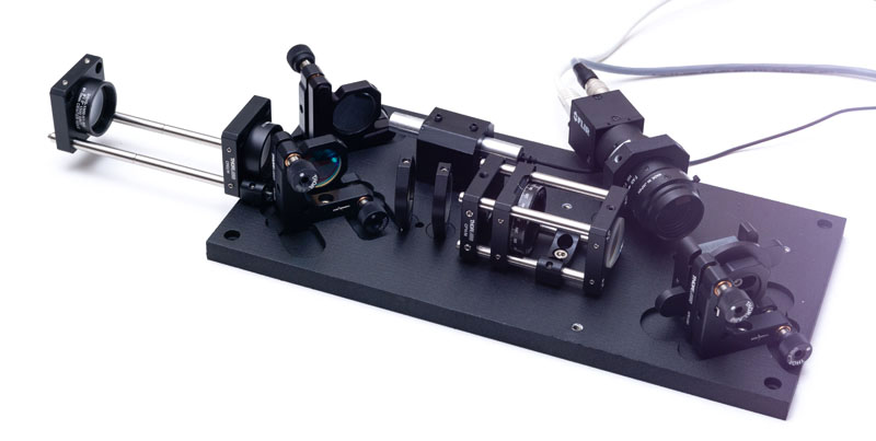
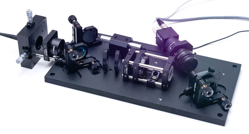
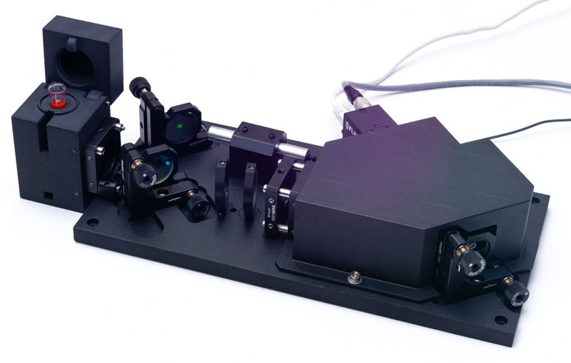
Before we dig into the assembly procedure of the setup, it is important that we review together the different parts that compose the spectrometer. Take a look at the image below:
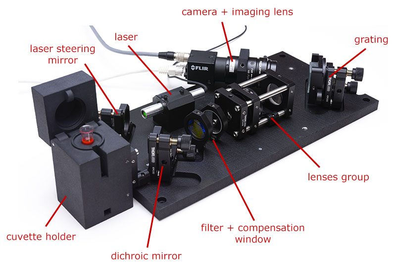
The laser module emits green collimated light that bounces on the steering mirror and reaches the dichroic mirror. The dichroic mirror has a very nice effect: it reflects green and blue light but transmits yellow and red light. This is why a dichroic mirror is also sometimes called a dichroic beamsplitter, because it splits light into a reflected and transmitted component. Since the laser is pure green, it is almost integrally reflected into the cuvette holder (efficiency of reflection is about 98-99%).
The cuvette holder is an assembly that comprises a lens group dedicated to focus the light into the test vial as a very small spot of a few micrometers diameter. This is where the Raman effect occurs : a very small fraction of the green light is transformed into red or yellow light through a process called inelastic scattering. This effect is very small, only 1:108 to 1:1010 of the photons are converted. The exact color of the light re-emitted will bring information on the composition of the liquid analyzed.
Scattered light (both Raman and non-Raman) will be re-emitted in roughly all directions and a part of it will be caught by the lens group of the cuvette holder and will collimate again. Just for your info, this optical configuration of the spectrometer is called the backscattering method. Other methods exist but this one is extremely robust in terms of alignment. The scattered light will be separated one more time by the dichroic mirror and the Raman components, along with 1-2% of green scattered light will pass through the mirror. Note that 1% is still much larger than the 1:108 to 1:1010 we previously discussed and we have to get rid of it using the edge-pass filter. As both the dichroic mirror and edge-pass filter will slightly shift the beam laterally because they are thick pieces of glass, we use a compensation window to bring the signal symmetric to the optical axis before it hits the lenses group.
The lenses group will focus light onto a thin slit of 50 µm × 2 mm and re-collimates the light exiting from the slit to feed it to the grating and imaging lens. The size of the slit controls the resolution of the spectrometer. This version of the spectrometer uses a 50 µm slit and the more advanced version uses a 10 µm slit.
The light will then be split by the diffraction grating into its various colors, just like a prism would do but in reflection. Light is then caught by the imaging lens and imaged on the camera as many replicas of the slits, one for each wavelength of the Raman signal.
It is important that you familiarize yourself with these terms before you proceed to the assembly. If you would like to know more about how the spectrometer works, please consult our technical articles.
Finally, please respect the following rules at all times:
- Never touch the surface of the grating with anything. Eventually blow gently compressed air to remove dust but do not attempt to scrub the surface with anything
- Wear powder-free gloves when handling optical components. If necessary, it is possible to clean them using distilled water and then analytical grade iso-propanol on optical tissue available at Thorlabs.
- Never look into the laser! Remove rings, watches or any jewelry that may reflect the laser light. Although the laser used here is class 3R, it is still excessively dangerous for the eyes. During assembly, laser safety goggles may be accessible to all persons working in the same room.
The assembly procedure described here shall be performed at your own risks. In no case the author shall be taken liable for the intentional or unintentional damages caused by the application of the present assembly procedure or operation of the spectrometer.

Now that everybody has been warned, let us start with the assembly now!
Step 1/ We will start with the lenses group:
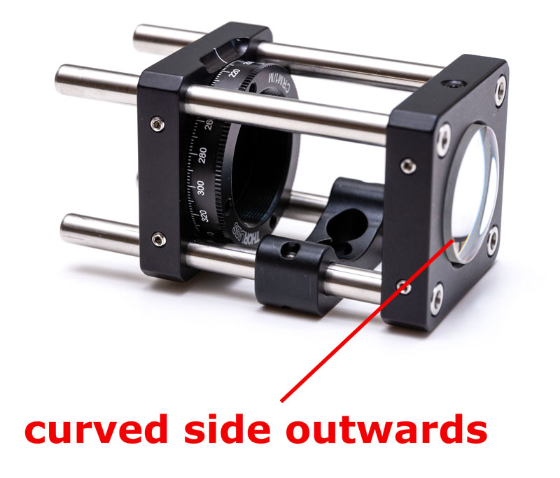
Take a CP35/M cage and four ER3 3″ cage rods. Assemble the rods such that they are flush with the cage mount (such as shown on the right of the figure). Insert a CP02B bracket but do not tighten it yet. Insert the 50 µm slit into the CRM1/M rotating cage and secure it with a retainer ring (use a SPW602 spanner wrench for that). Place the rotating cage at roughly 1″ of the end of the assembly and tighten only one of the screw at this point as we will adjust the position of the cage in a minute. Pay attention that the tapped hole of the CRM1/M cage should be on the same side as the CP02B bracket. Insert the 50 mm achromat lens AC254-050-A into the CP35/M cage with the most curved side outwards and tighten gently the set screw.
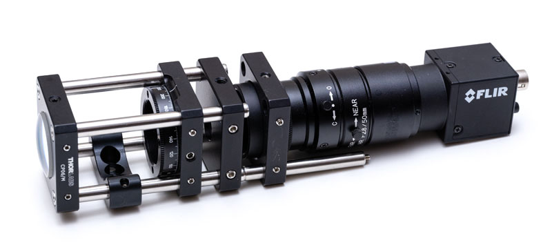
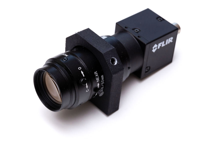
Step 2/ We will now align the slit in regards to the lens using the camera lens:
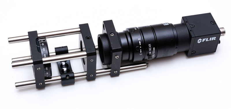
Add two temporary ER2 2″ rods on the side of the lens. Connect the camera to the machine vision lens. Set the lens to the infinite (FAR direction), fully-open (O) positions and tighten the adjustment screws to lock the settings. Connect the SM1A36 adapter and the SM1L05 extension tube to the lens. Add a CP36 cage to the lenses group and insert the machine vision lens as shown on the figure. Tighten the CP36 cage.
Now connect the camera to your computer and run the acquisition software. Set the frame rate to 10 fps, gain to zero and increase the exposure time until you see a signal on your monitor. You may have to orient the assembly towards a light source to see something but a daylight lit room should normally be enough. Image of the slit will most probably be out of focus and slanted. Orientation of the slit is not an issue at this stage. Slide the CRM1/M cage on the rods until the image is perfectly sharp on your monitor. Eventually zoom-in to see the details of the edge. Once in-focus, tighten all the screws of the CRM1/M cage. You may have to practice a little bit in keeping the focus while tightening the screws.
Here you basically aligned the slit at the focal position of the first lens using the machine vision lens as a reference to infinity. Ideally, one would use an autocollimator to do that but these are pretty expensive pieces of equipment and are not really mandatory in this case. By the way, there is a rule in optics which says that once you have aligned something, you should never touch at the set screws anymore. This part is aligned and you should not touch it again; if you have to untighten the screws at some point it means that you fucked up your alignment procedure somewhere! Here the alignment is relatively easy but sometimes you have to be clever and insert temporary mirrors and such.
Step 3/ We will now align the second lens:
Place the AC127-019-A achromat lens into the CP14/M cage plate and insert the plate at the back of the slit with the most curved part oriented outwards. Remove the temporary alignment system and place it behind the other side of the setup. Align the lens the same way as you just did previously.
Note that the image of the slit will appear larger because the lens is 19 mm focal length this time and was 50 mm focal length previously so you have a 5:2 magnification factor from the previous configuration. This is the basic of how a microscope works.
Step 4/ Take your baseplate:
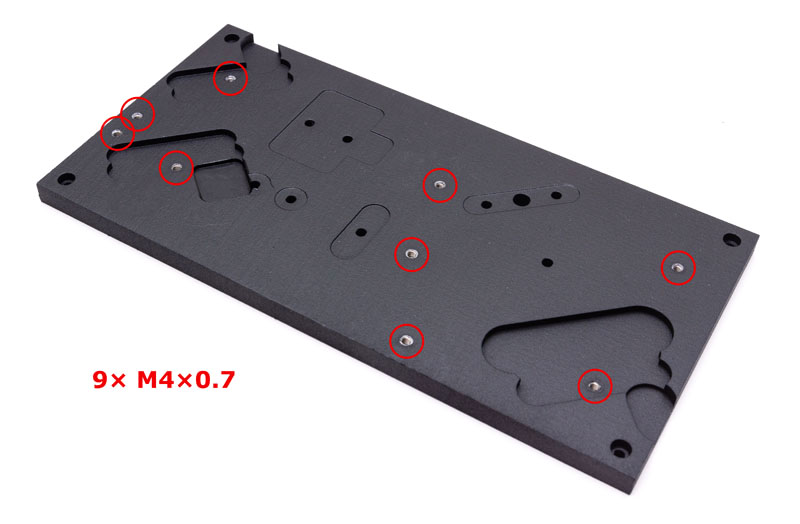
The baseplate accepts all the components of the system and places them in the right position, both laterally and vertically. As some of the cage plates and brackets have varying dimensions, some must be placed lower than others. This is why the baseplate is machined as it is.
Some of the holes of the baseplate should also be tapped with M4×0.7 holes. If you ordered the baseplate from 3D printing, you will have to tap the holes yourself. I recommend using helicoils steel inserts for this purpose. Check the tooling page for recommendation on helicoils placement.
We will now place the lenses group and the cuvette holder bracket on the base plate:
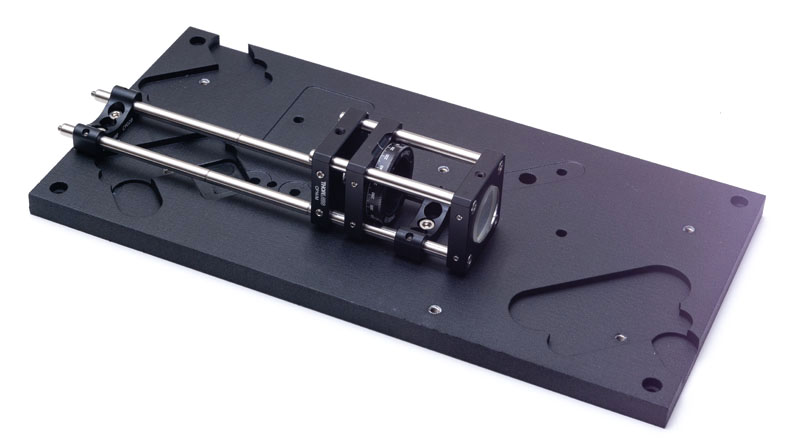
Use temporary ER6 rods to align the axis of the bracket and the lenses group. Secure the ER02B brackets using M4×6 screws and the CRM1/M using a M4×12 screw from below the baseplate. Remove the temporary rods once all the screws have been placed.
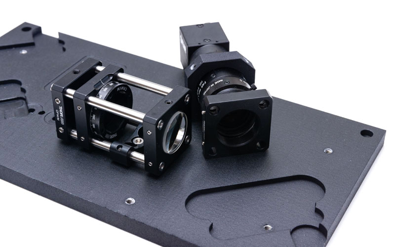
Step 5/ We will now add the camera to the baseplate.
First detach the machine vision lens from the camera. Insert the camera holder bracket from the rear and reconnect the camera asap. Pay attention that no dust enters the assembly. If you notice dust, flush them with gentle compressed air. Never scrub the lenses or the camera window!
Three of the holes of the camera bracket are designed to hold nylon-tipped set screws and two other holes are designed to fasten the bracket to the base plate. You should tap all these holes to M4×0.7 if you ordered the part in 3D printing but only the holes designed to fasten the bracket to the base plate should have helicoils. The three other holes will have low stress as they are only use to prevent the machine vision lens from moving.
Add the machine vision lens to the baseplate using two M4×12 screws from below but do not tighten them yet:
Use a temporary CP02/M cage plate to set the camera along the correct axis. You should be able to move the camera from left to right gently as well as back and worth until you see that it fits tight against the CP02/M cage plate. Tighten the camera holder bracket but leave the nylon-tipped set screws untightened at this stage.
Use a carpenter level to set the proper orientation of the camera and tighten gently the nylon-tipped set screws (check that your table is horizontal before!).
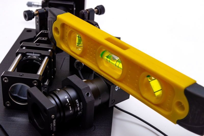
The idea of this part of the assembly is to orient the sensor horizontal with the base plate. Here we used the housing of the camera as a reference. In my experience, camera sensors are relatively well aligned to the housing so this is good enough for what we have to do. Remove the temporary cage plate.
By the way, if you notice some wobble in the machine vision objective, contact Thorlabs immediately. This is an issue with some of the lenses that I already met in the past and you should ask for a replacement part as this one will be unusable for the spectrometer.
Step 6/ Now place the grating in the KGM40 bracket and the KM100 kinematic plate. Fix the kinematic base to the base plate using a M4×10 screw.
You will notice that Thorlabs gratings have an arrow drawn on their side. This arrow should be oriented away from the camera as shown here:
Note: starting from revision 1 the KGM40 part was replaced by custom part #2020-15. The grating should be glued on the part using epoxy glue and fishing wire to provide the recommended thickness of glue. We recommend using Scotchweld 2216 with 120 µm fishing wire. Degrease properly the surfaces in contact using acetone and outgas the glue for 1 minute for maximum adhesion. The grating should sit square to the two extrusions to be centered correctly in the optical path.
Step 7/ We can now add all the other components on the baseplate:
Put the laser in its holder. Again, if you 3D printed the holder, only the holes designed to fasten the holder to the baseplate should have helicoils. The two holes on the top can have normal M4×0.7 taps as they receive nylon-tipped screws. Tighten the laser using two nylon-tipped screws at roughly the position shown in the image. Place the laser holder on the baseplate using two M4×12 screws.
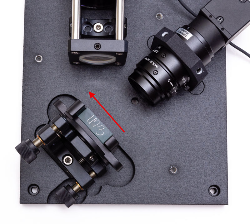
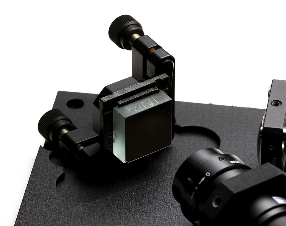
Add the steering mirror and the dichroic mirror using two KM100 kinematic plates using two M4×10 screws. Pay attention to the orientation of the dichroic mirror, the shiny surface should face the incoming beam.
Add the FELH0550 edge filter and the WG11050-A compensation window in their FMP1/M mount using two M4×12 screws from below. Pay attention to the side of the edge filter as the arrow drawn on the housing should face the lenses group. Orient the elements as shown on the image.
Step 8/ Add two ER6 extension rods with the two DG10-1500-H1-MD ground glass alignment disks mounted in CP02/M cage plates as shown on the image. We will use these ground glass disks to align the laser beam with the optical axis of the system:
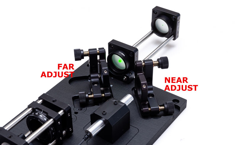
The idea is to center the laser beam in both holes of the ground glass disks.
Once the laser has been turned on, you can adjust the near side interception with the steering mirror and the far side adjustment using the dichroic mirror. This is an iterative procedure because moving the far adjustment will slightly affect the near side as well, but only by a small amount due to the leverage.
Once the laser is correctly steered, you can remove the temporary rods and ground glass disks.
Step 9/ We will now align the spectrometer and the filters.
To do this we will have to send light to the system using a fiber. Create an assembly using an AC127-019-A lens mounted in a CP14/M cage plate and roughly collimate a M53L02 600 µm fiber using a SM1SMA adapter mounted in a CP02/M cage plate with two ER2 rods. Put the collimated fiber assembly on the setup as shown on the image:
Note that I used slightly different components as those suggested because I did not have a 600 µm fiber available. I do not recommend the solution I used however because it is inferior and more expensive.
Put the other end of the fiber next to a fluorescent lamp and start the camera software. Adjust the exposure settings so that the image does not saturate. Turn the crosshair mode on in the acquisition software to aid the alignment.
You should see something looking like this (schematized):
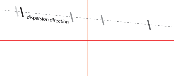
First rotate the grating using the KGM40 plate until the dispersion direction is aligned with the crosshair. You will eventually have to tune the signal vertically using the kinematic plate knobs. Once aligned, tighten the screw of the kinematic plate to hold the KGM40 plate in place.
You should see something like this (schematized):

We will now orient the slit such that it is vertical. Turn the CRM1/M plate until the slit is perfectly vertical and tighten the set screw on the side (next to the camera).
Step 10/ We will now tune the spectral range of the instrument.
We use the fluorescent lamp because it has two peaks located at 542.4 nm and 546.5 nm. With a 532 nm laser this corresponds to 360 cm-1 and 498 cm-1. We would like to be able to reach signal at 500 cm-1 so we will tune the edge filter to cut just between the two peaks. We have to be sure to reject all the intense laser light that is scattered to prevent stray light from entering the spectrometer part of the instrument as it would generate stray light.
Edge filters can be tuned by setting them with an angle relative to the incoming beam:
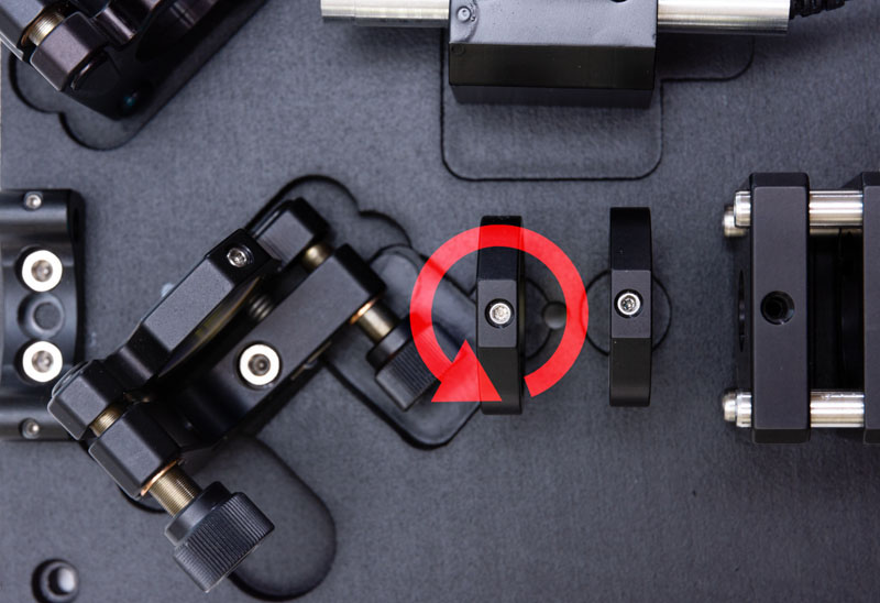
Rotate the edge filter until you see both peaks and then fasten the edge filter such that you see the peak at 546.5 nm but not the peak at 542.4 nm.
If you do not see any changes when turning the edge filter it may be because the grating is too tilted. Adjust the position of the grating using the KM100 horizontal knob until you get it at the right position.
Once you have set the filter correctly, bring the 546.5 nm peak close to the edge of the sensor but without clipping it. That will maximize the wavenumber range available by the sensor and we should now cover the 500-3500 cm-1 range with the instrument.
Step 11/ We are now almost done! We still have to get the wavenumber scale right.
To do this, use a neon lamp and feed the light into the setup using the fiber. You will have to increase the exposure time on the camera. Process the data using the peak position given here:

Using Excel or Matlab, determine a linear regression law to convert from pixels to wavelength. Wavelength to wavenumber conversion is given using the formula (wavelengths in nm and wavenumber in cm-1):
Step 12/ You can now remove the fiber alignment assembly and replace it with the cuvette holder. Also install the cover using three M4×10 screws and washers:
Set the frame rate to 10 fps in the camera software and the gain to maximum. Insert a cuvette with i-PrOH or acetone and turn on the laser. Optimize the amount of signal by using the horizontal knob of the dichroic mirror kinematic plate.
Center the signal vertically using the grating kinematic plate knob and change the camera settings to be 64 px height and Mono16 mode. Save the settings in the User Channel 0 of the camera to default to these settings the next time the camera is plugged in.
To acquire data, uncheck the frame rate checkbox in the camera acquisition software and set the camera exposure to 10 sec, gain 0. Eventually increase or decrease the exposure time depending on the substance you are analyzing.
To get a spectrum, save the image and process it using the Matlab software. You may also average several images to increase the signal-to-noise ratio.